Learning electronics from scratch with an ESP32 and an LED lamp.
In progress
I started teaching myself electronics today. I had Claude put together a sequence of projects to work through, and the first one is a desk lamp.
Step one was flashing the ESP32, which was straightforward. I’d already set up and configured the project folder, so today was just adding a main.cpp in the src folder. The moment I added #include <Arduino.h> I got an error. Copilot helped me track it down: there was no c_cpp_properties.json with the C++ compiler settings, and no .vscode folder for it to live in. I created both, and the code ran: blinking the onboard LED on and off every 500ms.
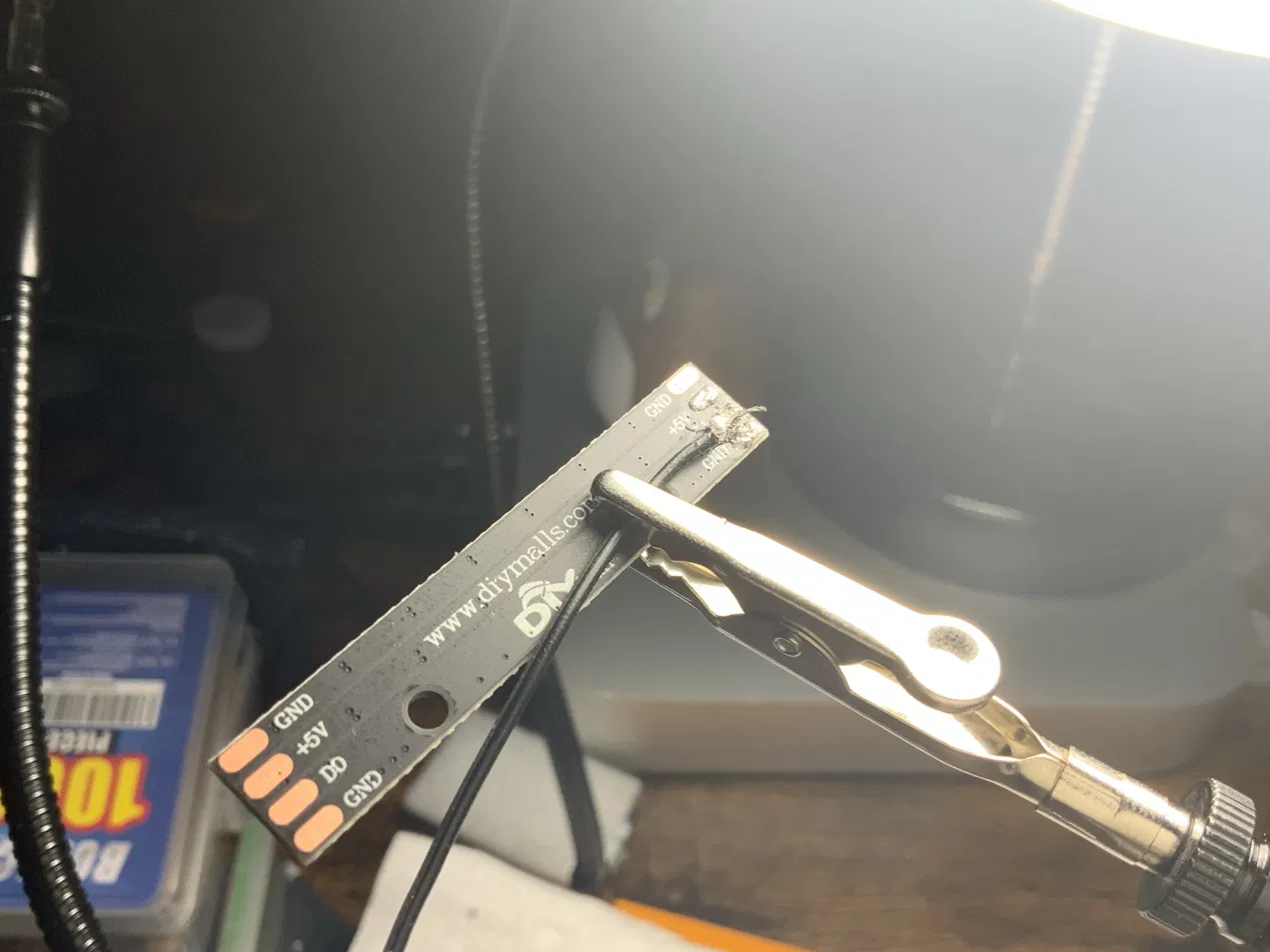
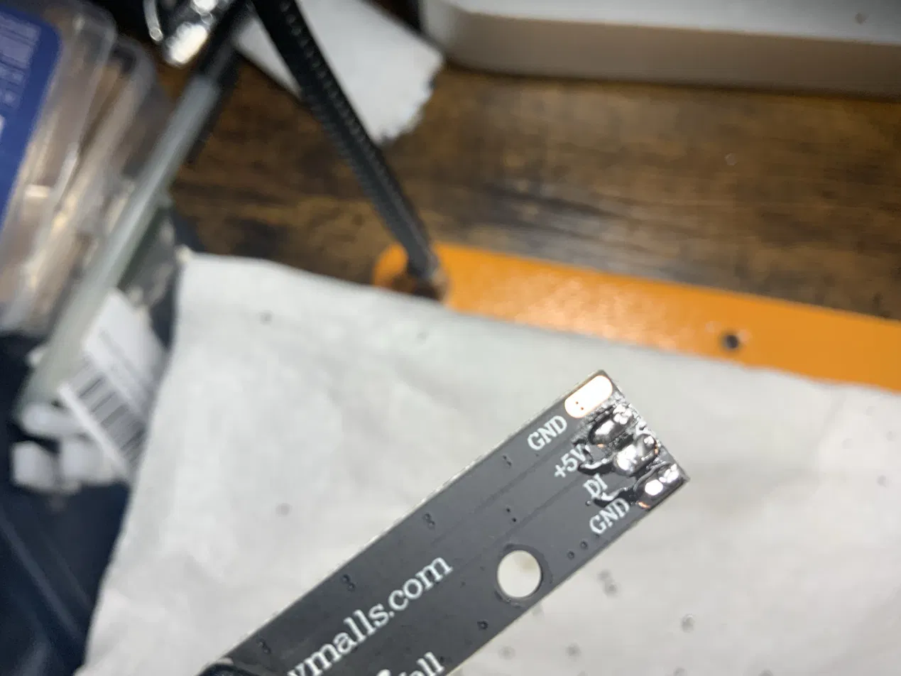
Next was connecting an LED stick to the ESP32. The stick didn’t come with any pins or wires, just bare pads, so I had to solder three male jumper cables to it. It was the first time I’d ever soldered. I also had to look up pinout diagrams for both the ESP32 and the LED stick to work out what goes where: GND, DI, and 5V.
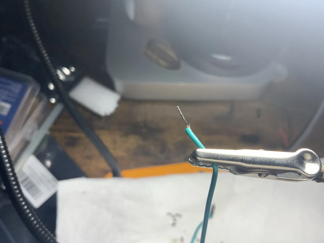
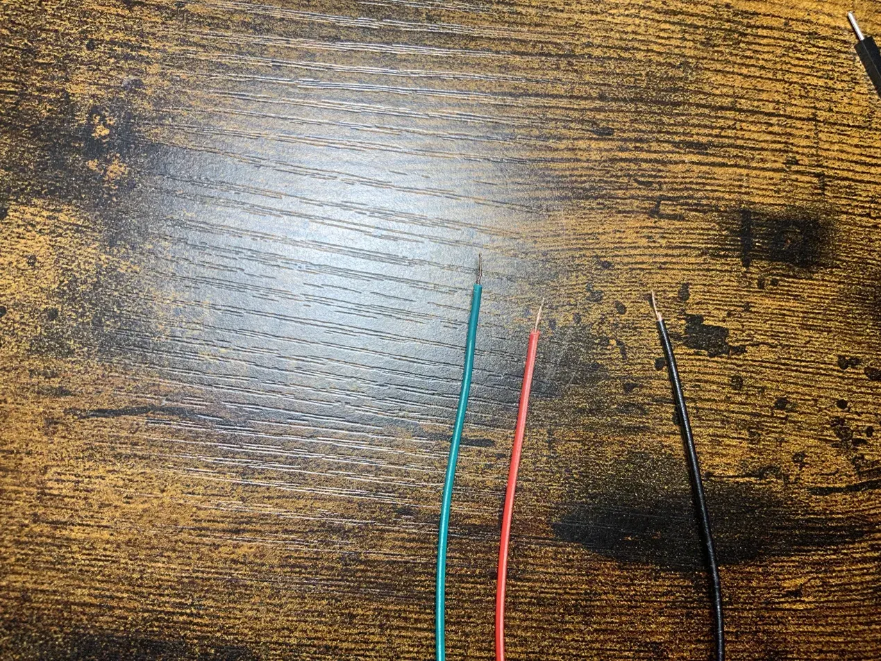
I stripped one end of each cable and twisted the strands. Three wires: red, black, and green. Then I had to tin the ends.
First problem: my soldering iron wouldn’t turn on. I’d bought the Fanttik cordless one. I found a video suggesting that you have to press the tip firmly into the base, and that fixed it.
Then I had to actually learn to solder. I struggled with this a lot. My solder kept balling up on top of the wire instead of flowing into it.
What I eventually learned is that soldering doesn’t work the way I assumed. You don’t melt solder on the iron and drop it onto the wire: the solder never touches the tip at all during the actual joint. You heat the copper first, hold the iron against it for a few seconds, and then feed the solder into the hot copper from the opposite side. It melts on contact and pulls itself in. Solder flows toward heat, so the copper has to be the hot thing. If it’s not hot enough, the solder just cools where it lands and sits there as a dull lump, which is exactly what mine kept doing.
Knowing that didn’t fix it, though. Even with the right technique I still couldn’t reliably get the solder to flow into the copper. It took a lot of attempts before I got something usable, and I’ve got a long way to go.
Applying solder to the pads on the LED stick went better. I used the multimeter on continuity mode to check I hadn’t accidentally bridged any of the pads together, which came back clean.
Then I hit the wall. I held the jumper cable and the LED stick in the helping hands and tried to join the wire to the pad, and the wire just would not stick. That was frustrating. I had to keep reminding myself this was my first time doing any of this.
Overall it was fun, and the cordless soldering iron is genuinely cool.
Next steps
I’ve ordered an LED strip that comes with wires already attached and doesn’t need soldering, so I can get the lamp finished. I’ll learn to solder properly on a separate practice project rather than on the thing that’s blocking me.
1. Jumper wires prepared for soldering2. Stripping the green jumper wire3. LED stick held in helping hands4. Prepared red, black, and green wires
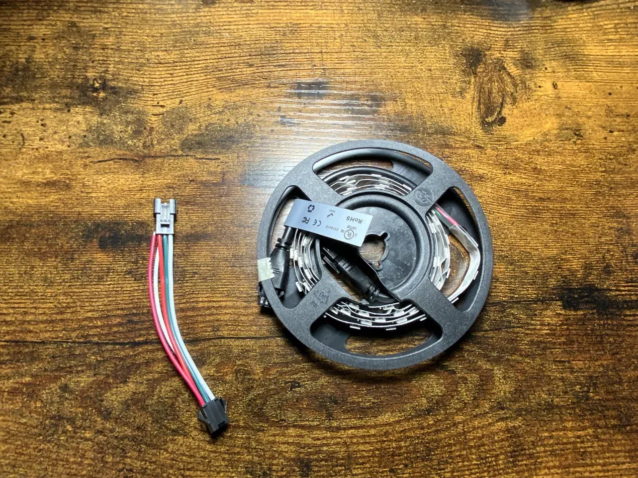
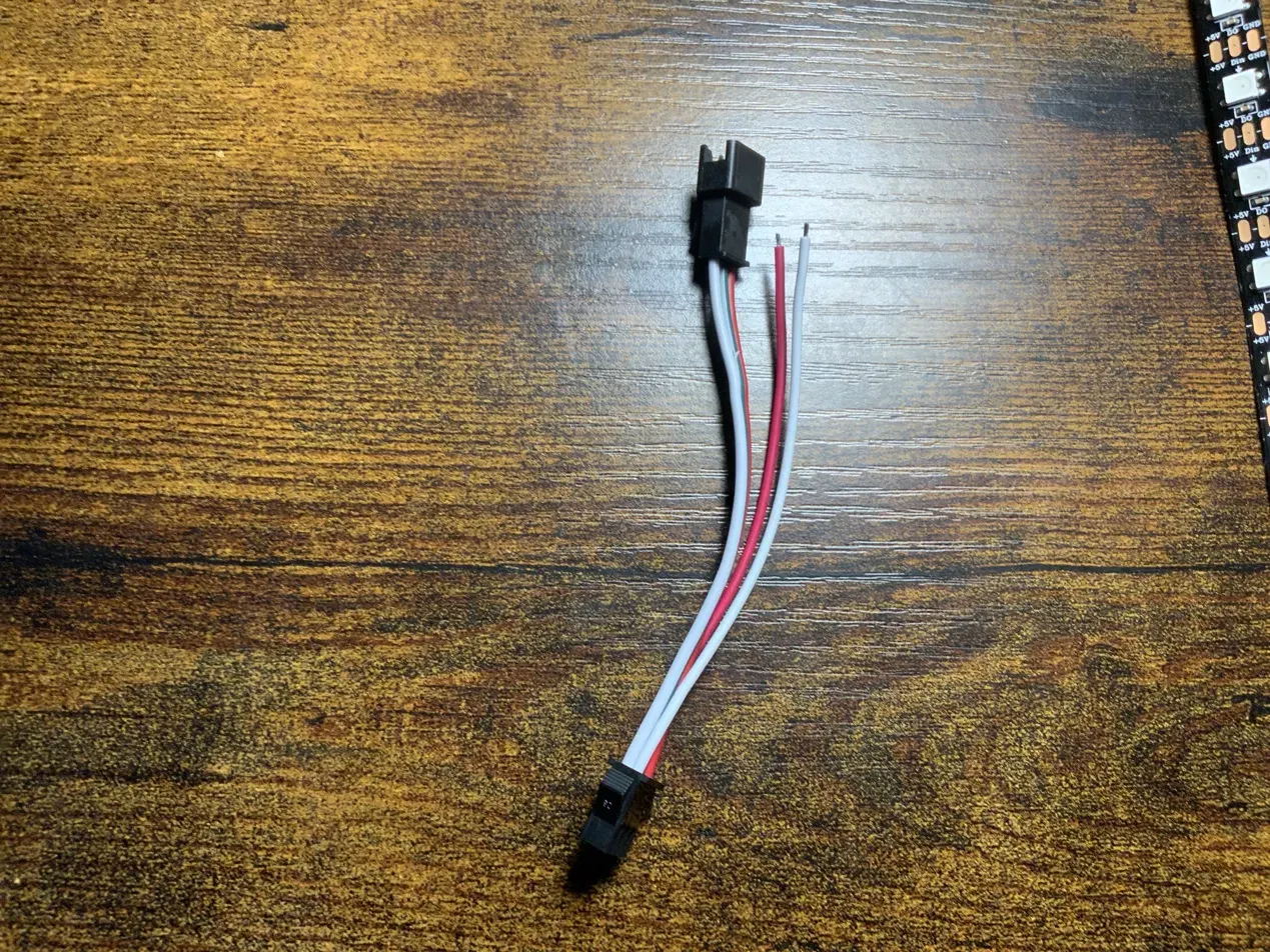
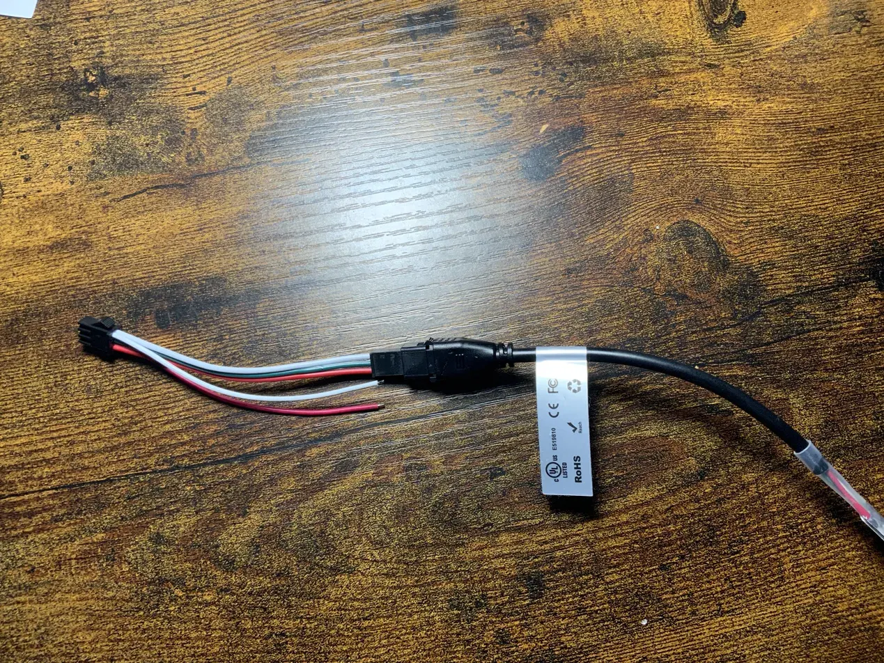
I got the new LED strip in (IMAGE ONE), the one that comes with wires already attached so I could skip soldering entirely.
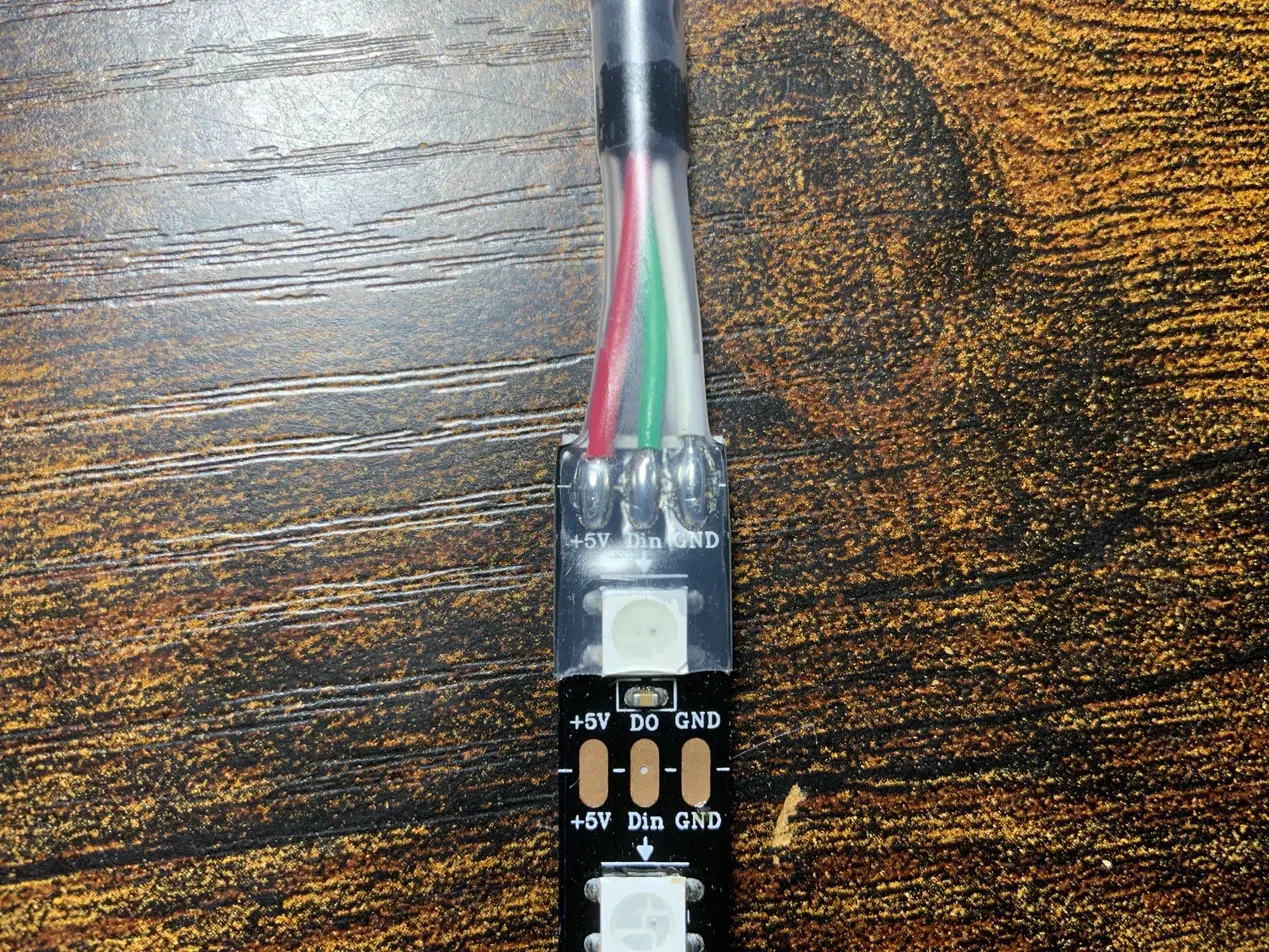
First task was figuring out which wire was which: +5V, Data In (DIN), and Ground (GND). That was easy to find printed right on the strip (IMAGE TWO): red → +5V, green → DIN, white → GND.
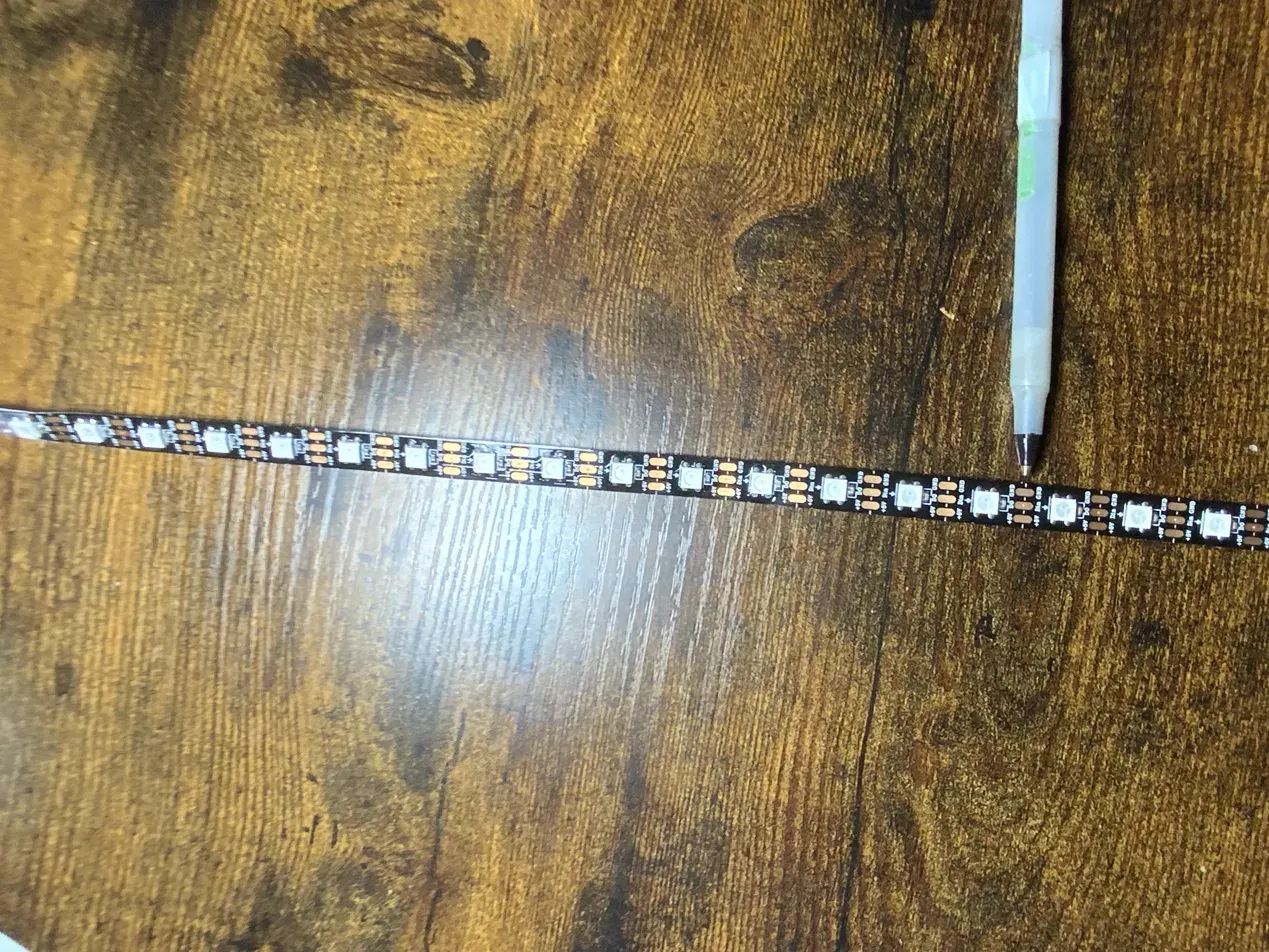
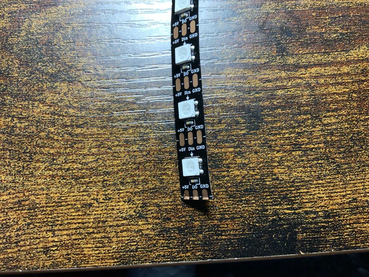
Next I had to cut the strip down to 15 pixels. The cut has to land right after the last 5V/DIN/GND pads on the 15th pixel, which I marked and cut with scissors (IMAGE THREE, IMAGE THREE-A).
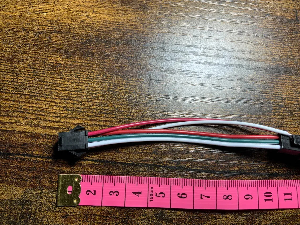
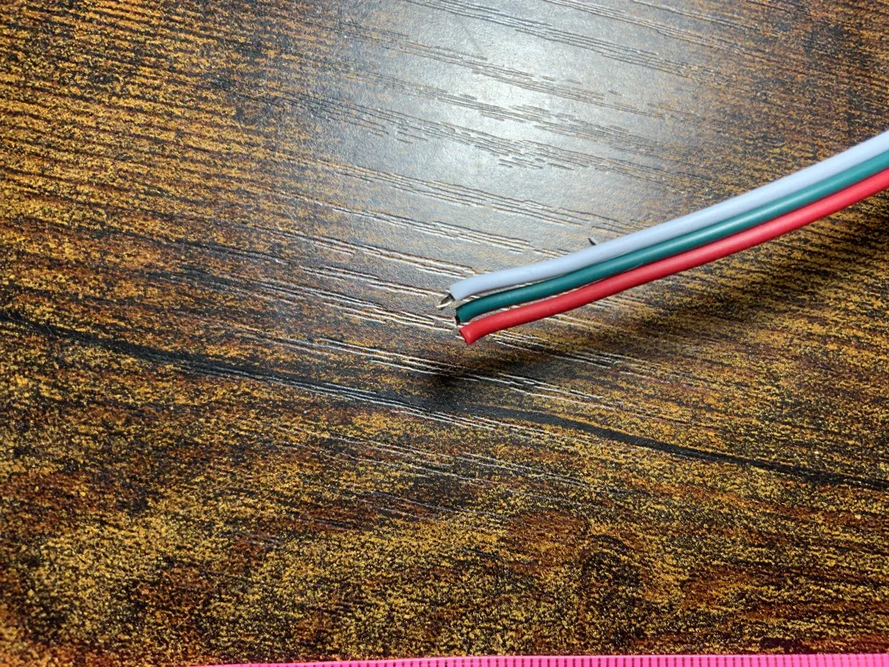
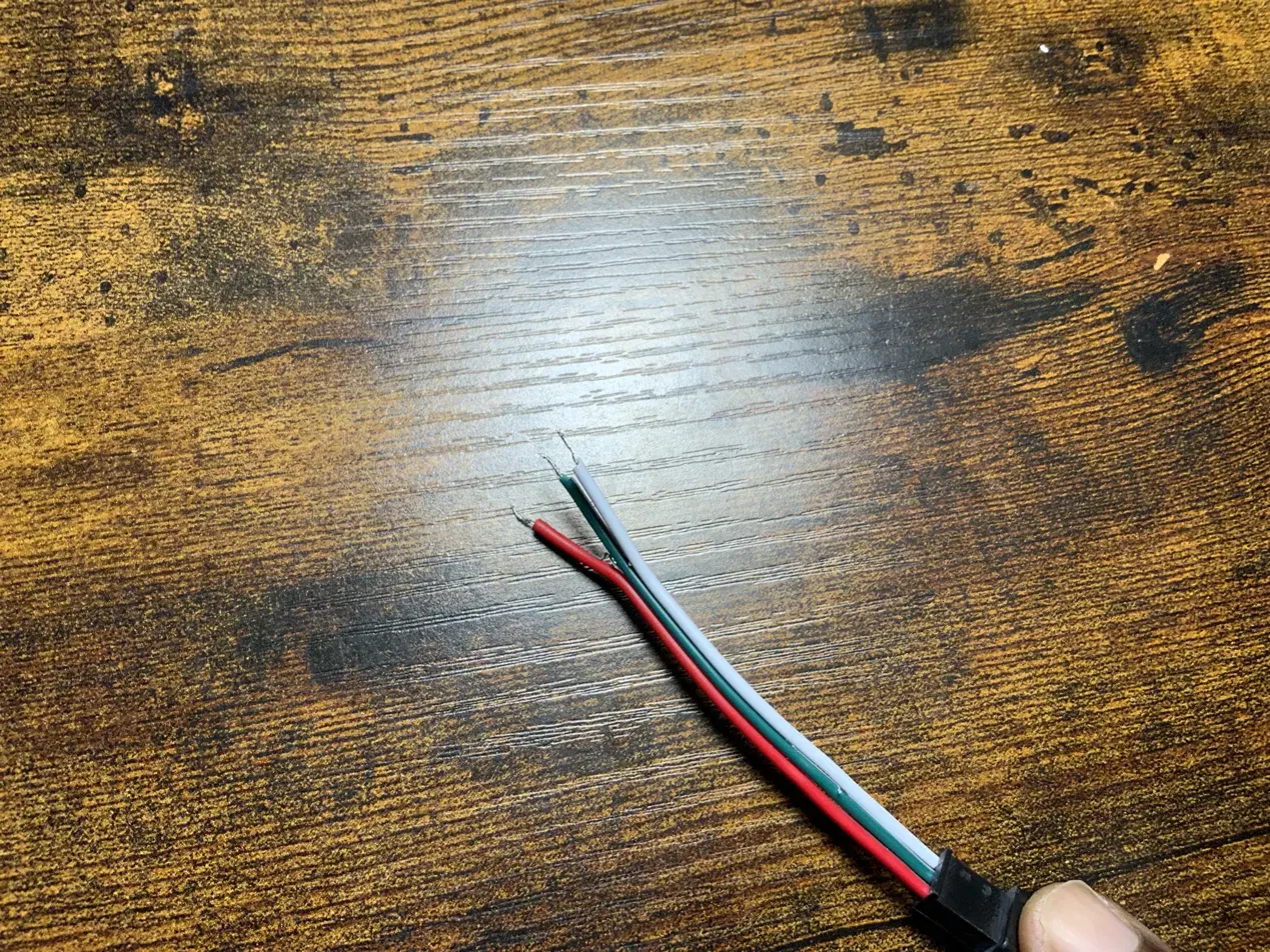
Then I attached the pigtail connector that came with the strip (IMAGE FOUR), onto the end that had 5V, DIN, and GND (IMAGE FIVE). I cut off the other end of the pigtail, about 1cm from the black head, to expose the wire (IMAGE SIX, IMAGE SEVEN). Using the Kaiweets wire stripper on the 22 AWG notch, I stripped the rubber off each copper wire and twisted the strands in my hand (IMAGE EIGHT).
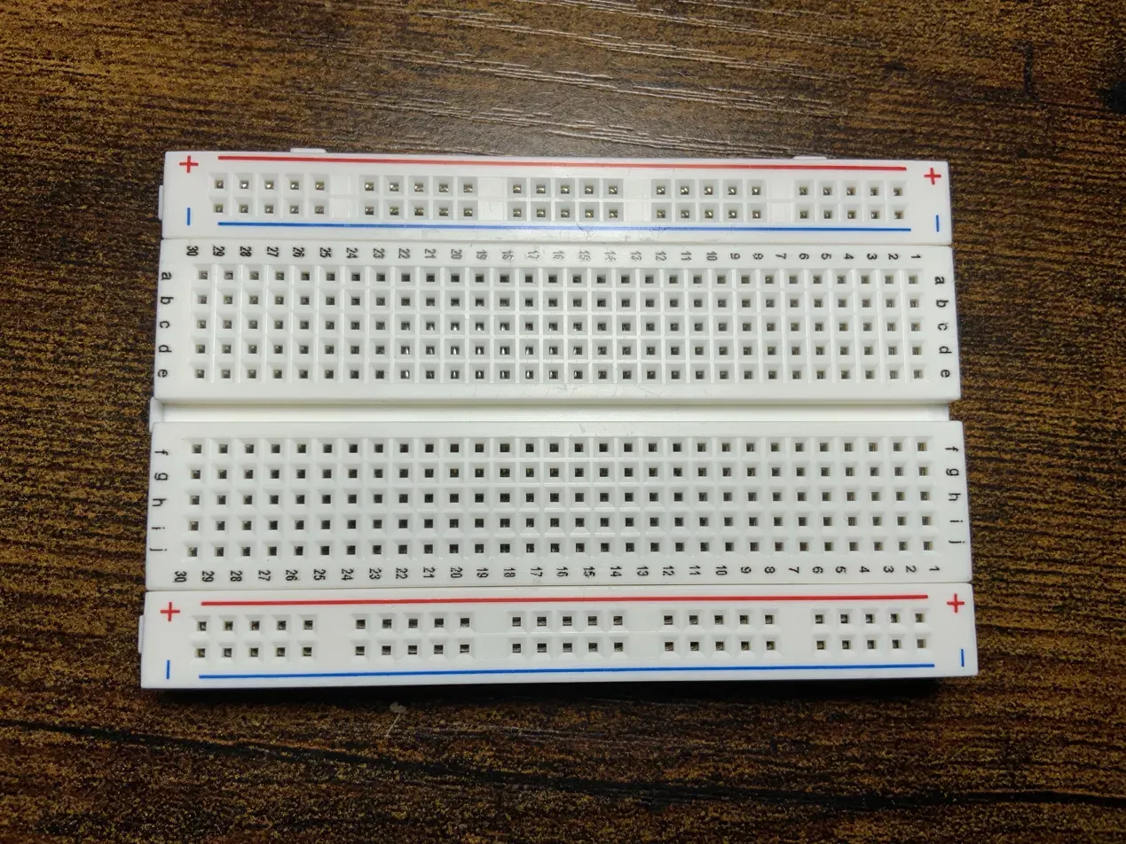
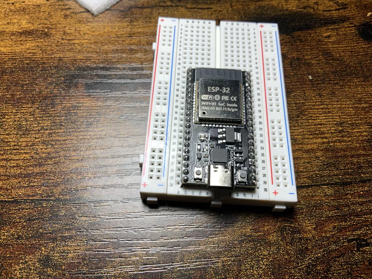
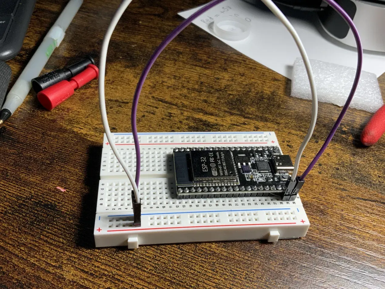
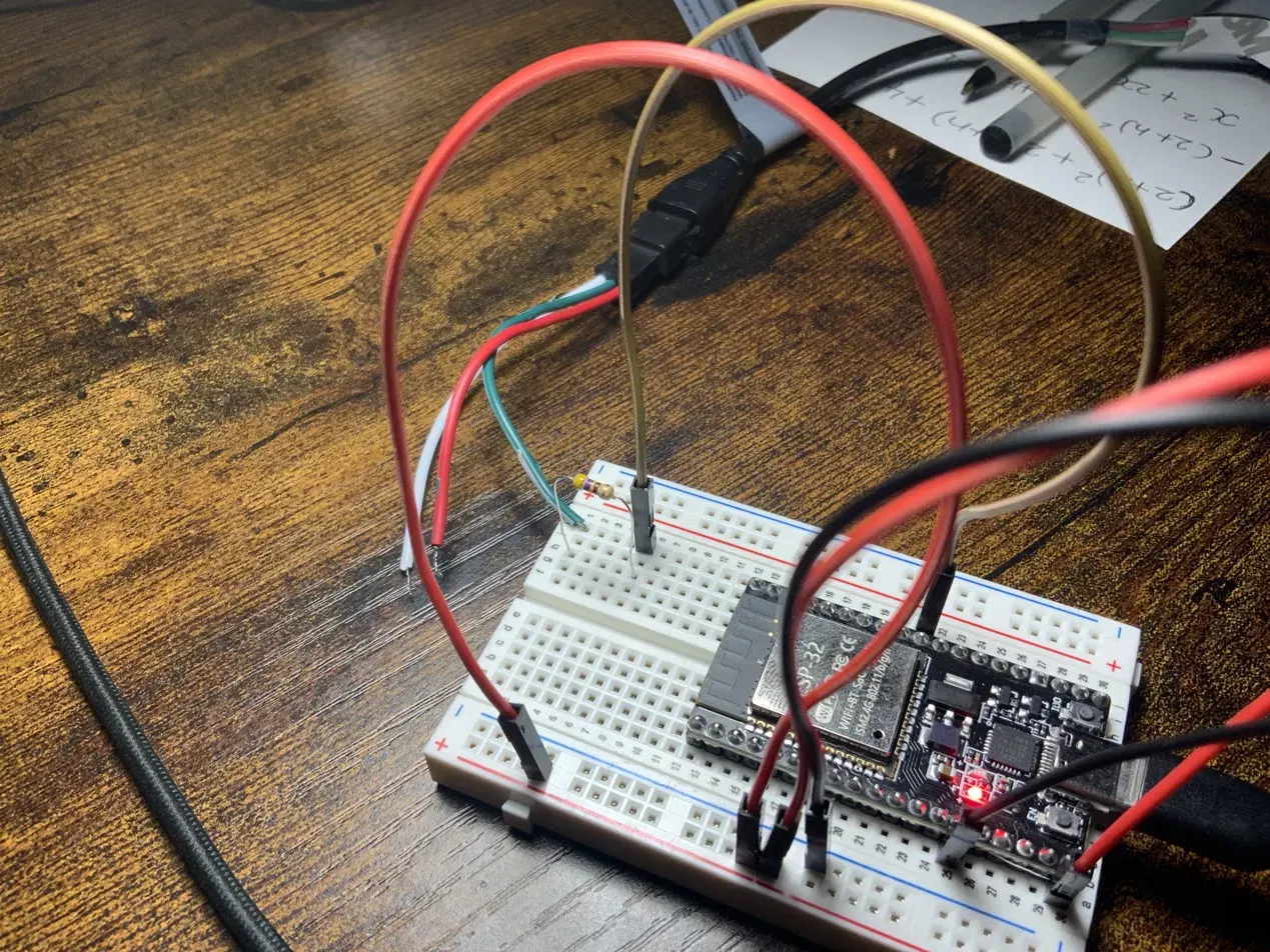
Then the hard part. I had the flashed ESP32 in hand but no idea where or how to plug the LED wires into it. After some back and forth with Claude, I understood I needed to go through a breadboard first (IMAGE NINE), which came with its own puzzle: figuring out which holes the ESP32’s pins should sit in. I seated the ESP32 between columns b and i, rows 11 to 30, with the USB port at the bottom for easier access.
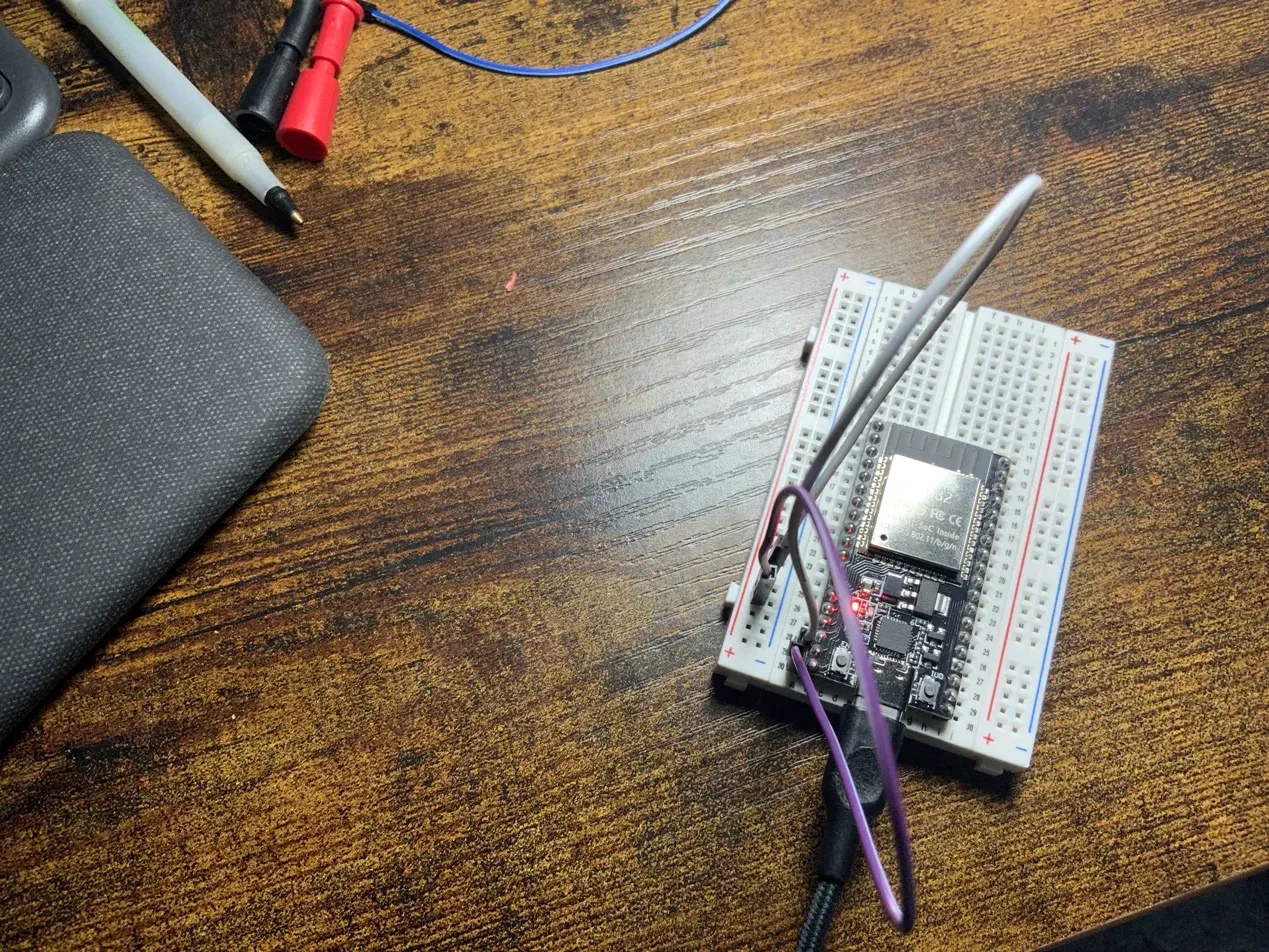
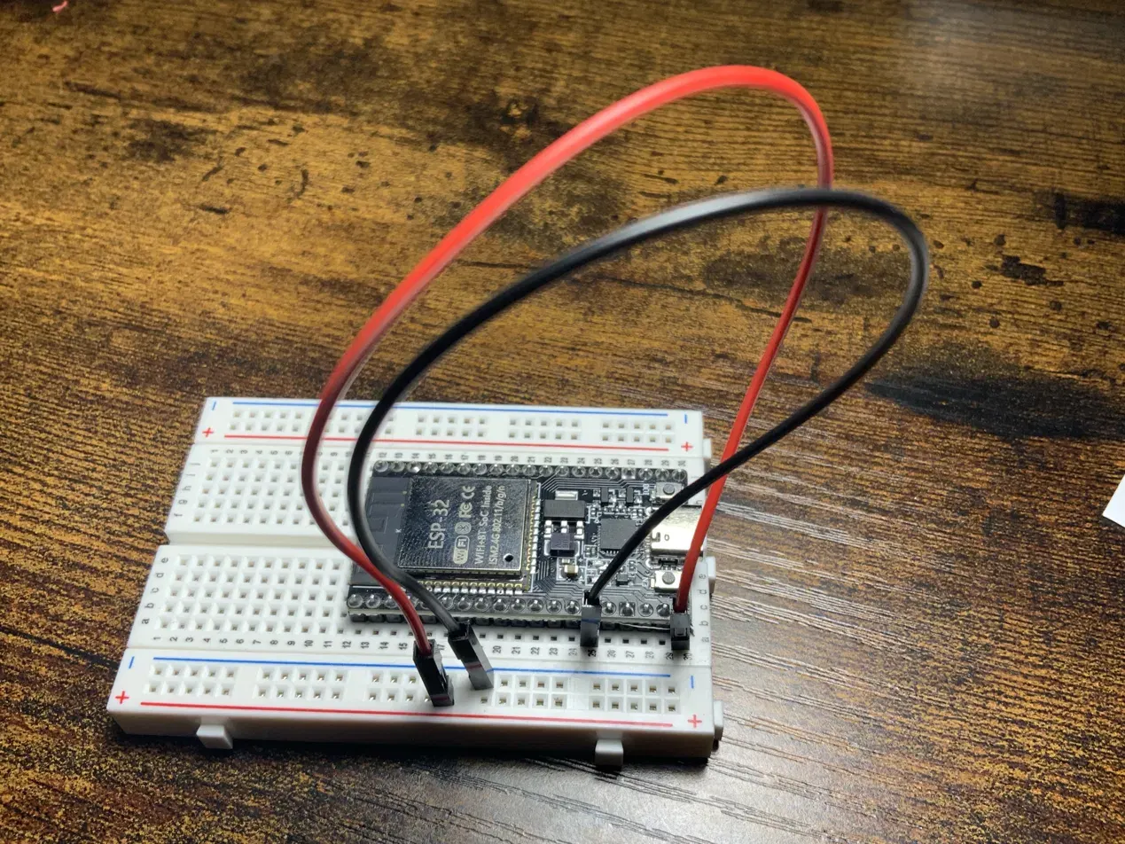
Using a jumper cable, I set out to find 5V on the ESP32. I plugged power and jumper cables into a30 and a29 (IMAGE ELEVEN), running the other end of each to the rails: a30 to the blue rail, a29 to the red rail (IMAGE TWELVE).
Then I got out the multimeter. First I had the INPUT and COM leads swapped, so I fixed that. Then I had to work out which voltage symbol to use, V⎓ or V~, and settled on V⎓ (DC).
The probe tips turned out to be too big for the breadboard holes, so I couldn’t get a good reading directly. I switched to feeding two jumper cables into the board and probing the exposed ends instead, which turned out to be the hardest part of the night. The readings stayed unstable no matter what I tried, and I repeated the process on both sides of the ESP32 with no luck. Without a reliable reading I didn’t want to guess which side actually had 5V, so I called it a night there.
Next steps
Get a stable multimeter reading on the ESP32’s 5V rail before wiring the LED strip in for real.
1. The new LED strip2. Pinout: red +5V, green DIN, white GND3. Cut point after the 15th pixel3a. Strip cut to 15 pixels4. The pigtail connector5. Pigtail attached to the 5V/DIN/GND end6. Other end cut to expose the wire7. Closer view of the cut wire8. Stripped and twisted copper strands9. ESP32 seated on the breadboard10. USB port positioned at the bottom11. Jumper cables in a30 and a2912. Cables running to the power rails
I started today’s session by going over the notes and issues from last time. The main thing I still wasn’t sure about was where GND and 5V were on the ESP32. I googled the board to find its datasheet and shared it with Claude. Claude suggested checking the pins with the multimeter in continuity mode.
Continuity mode is a quick pass/fail test for whether electricity can flow through a circuit or wire. I’d never used it before, so I did more googling and watched a YouTube tutorial. The meter sends a tiny current out of one probe and checks whether it comes back through the other. If there’s a metal path between the probe tips, it beeps; if there isn’t, it stays quiet. It answers a simple question: are these two pieces of metal the same electrical point? (How to Use a Multimeter: AstroAI DM6000AR Full Tutorial, Maddox Mechanic, Dec 5, 2025.)
I unplugged the USB cable from power, set the multimeter to continuity mode, and placed the black probe on the USB-C shell for ground. Then I touched the red probe to the ESP32 pins. The pins that beeped were b25, i12, and i18.
That explained the problem from last time. I’d put jumpers in a30 and a29, assuming b30 was 5V and b29 was GND. The 5V was right; the ground was wrong. Ground was actually at b25. With that sorted, I finally felt confident enough to continue. I’m glad I was patient. If I hadn’t been, I might not have seen a result later on.
I started the wiring with two jumpers:
b30 to the red positive rail
b25 to the blue negative rail
The probe tips were too big to fit into the breadboard holes, so I used jumper wires and tested at their other ends instead. With the multimeter set to DC volts, I got a reading of 4.79 V, very close to 5 V.
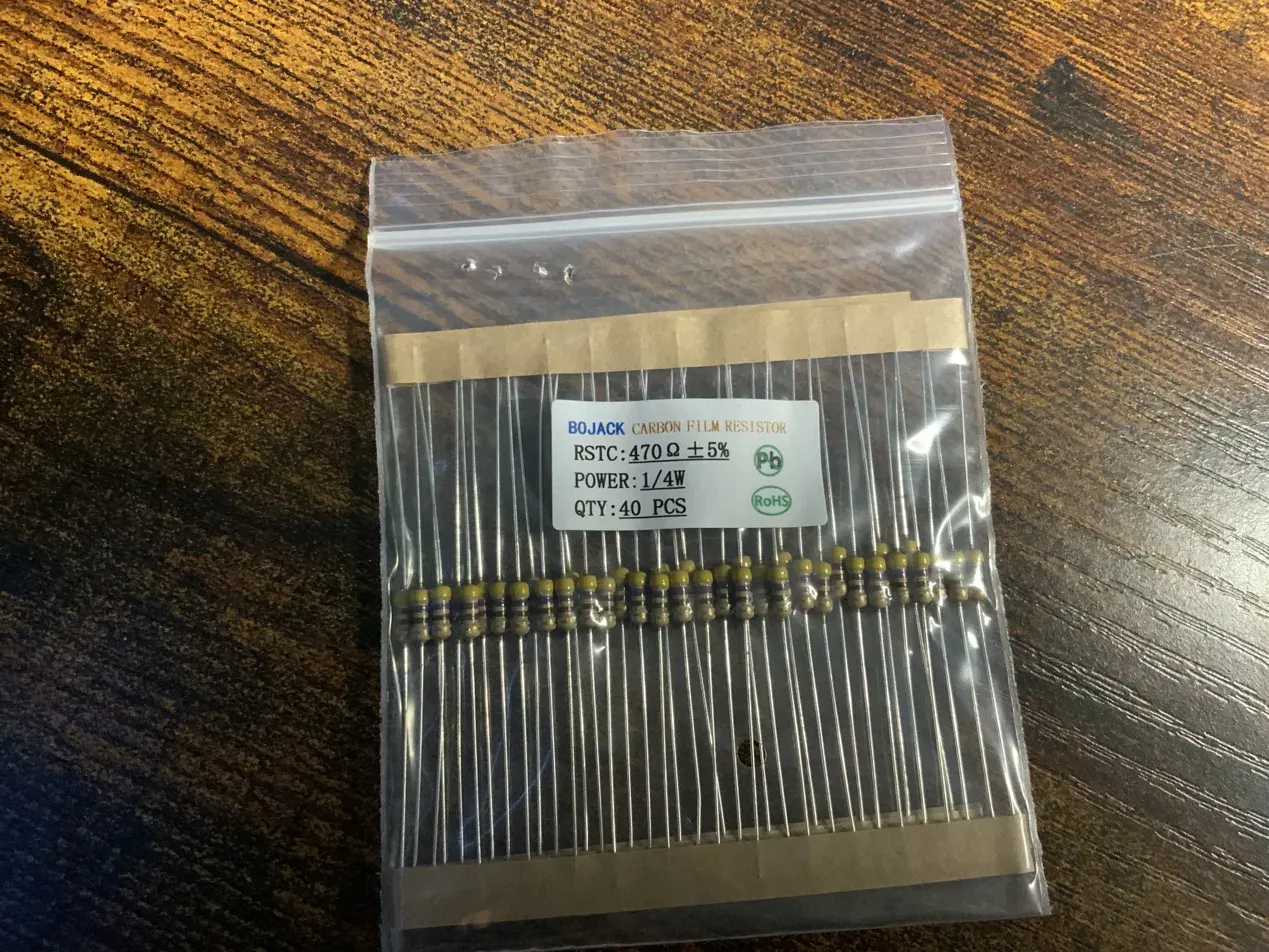
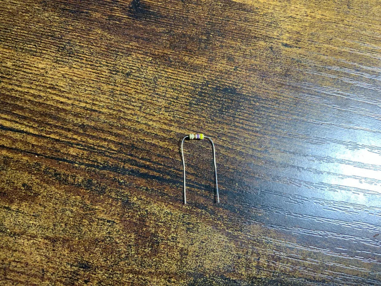
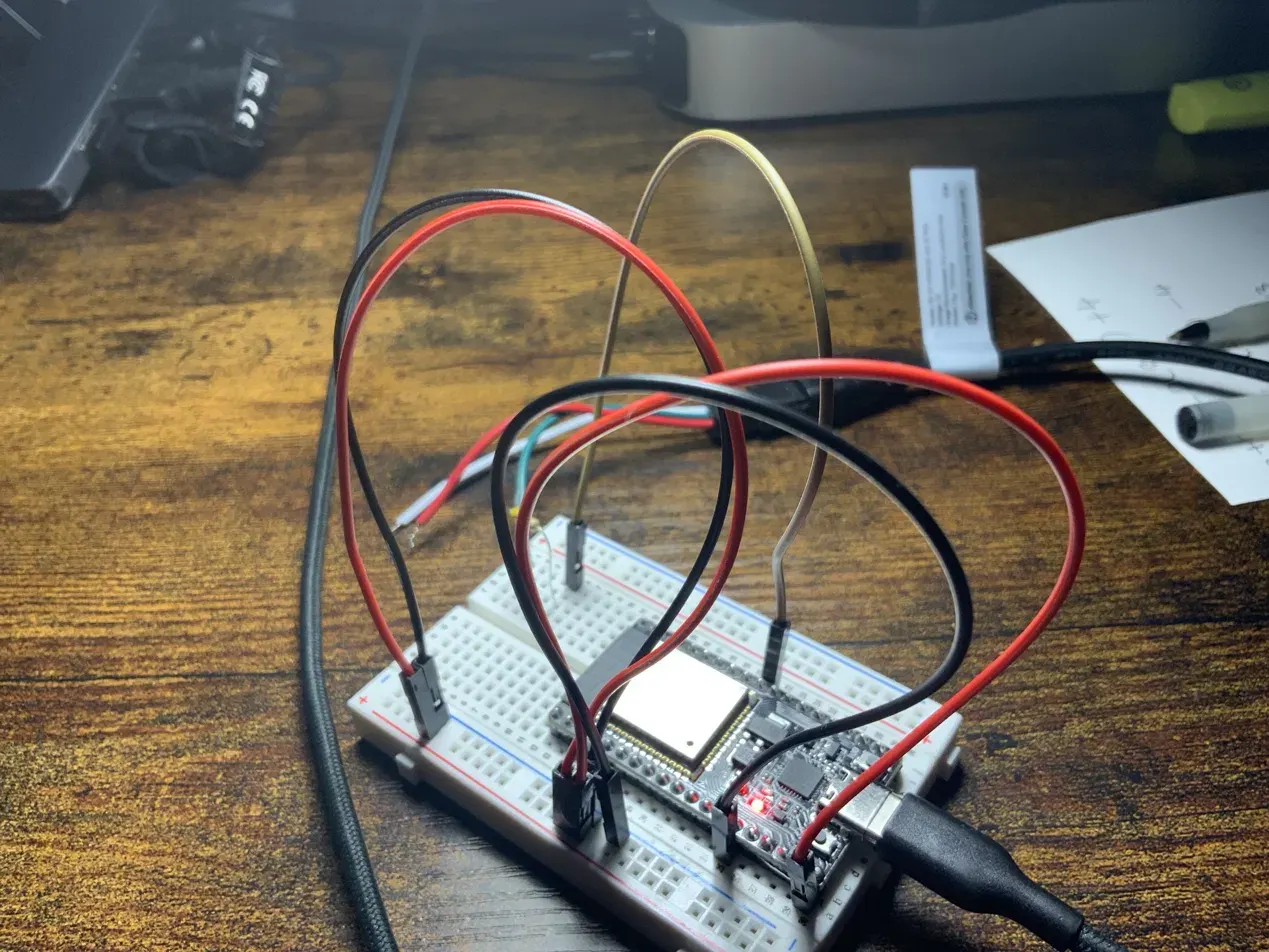
Next, I ran a jumper from j21 to j5 to bring GPIO 5 out to an empty row. I added a 470Ω resistor between h5 and h1. This was my first time using a resistor, so I had to read up on its colour bands to identify the 470Ω one. Once I had the right resistor, I got its legs into the breadboard.
The LED wires were short, so Claude suggested linking the power rails. I ran a red jumper from the bottom positive rail to the top positive rail, then did the same between the negative rails with a black jumper. I tested across the rails with the multimeter and got 4.78 V.
Then I connected the LED strip: green data wire to j1, red +5V wire to the top red rail, and white ground wire to the top blue rail.
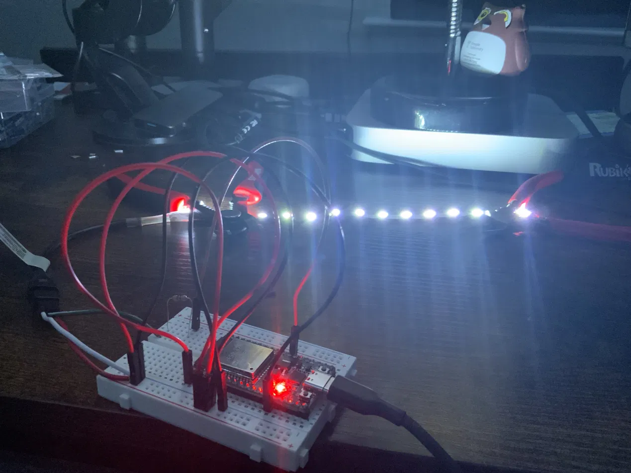
My first attempt to flash the board got stuck on “Connecting”. After a lot of troubleshooting, I discovered I was using a USB cable that couldn’t carry data. I switched to the cable I use to charge my Mac, and that worked. I checked that the board was connected with ls /dev/cu.*, then ran pio run -t upload from the folder containing main.cpp. The upload succeeded and the light came on.
The light was solid white rather than the warm colour in the code. That meant the strip had power but wasn’t receiving data. I noticed that the green wire was in the breadboard’s a–e block while the resistor leg was in the f–j block. Those groups are separate: the centre channel breaks the connection between them. Moving the green wire over to the f–j side completed the data path, but the light stayed white.
The last thing I tried was moving the data line off GPIO 5. GPIO 5 is a strapping pin, which the ESP32 uses during boot, so it seemed worth ruling out:
Moved the yellow jumper from j21 to j23 (GPIO 16).
Changed the code to const int DATA_PIN = 16;.
Reflashed the board.
There was no change, so GPIO 5 wasn’t the problem either. I didn’t stress too much. I’ll have to pick this up again, but I’m glad for everything I learned, and glad the light came on at all.
Next steps
Work out why the LED strip is staying white instead of receiving the colour data.
1. Checking the voltage across the rails2. Reading the resistor colour bands3. The 470Ω resistor in place4. Linking the positive rails5. Linking the ground rails6. The LED strip lit up